Performance Differences Between Quartz and Lithium-Based Piezoelectric Wafers describes how quartz and lithium-based materials—primarily lithium niobate (LiNbO3) and lithium tantalate (LiTaO3)—convert mechanical stress into electrical signals and respond to temperature, frequency, voltage, and vibration. In practice, Single Crystal Quartz Wafers are often selected for frequency stability and low aging, while lithium-based wafers are valued for stronger electromechanical coupling, wide bandwidth, and high-frequency acoustic devices. Choosing the correct wafer can improve oscillator reliability, RF filter yield, sensor sensitivity, and total manufacturing cost.
For CQT customers, this material decision directly affects device design, electrode patterning, wafer processing, and final frequency control. A qualified supplier should provide crystal orientation, thickness tolerance, surface finish, flatness, inspection data, and traceability—not just a material name.
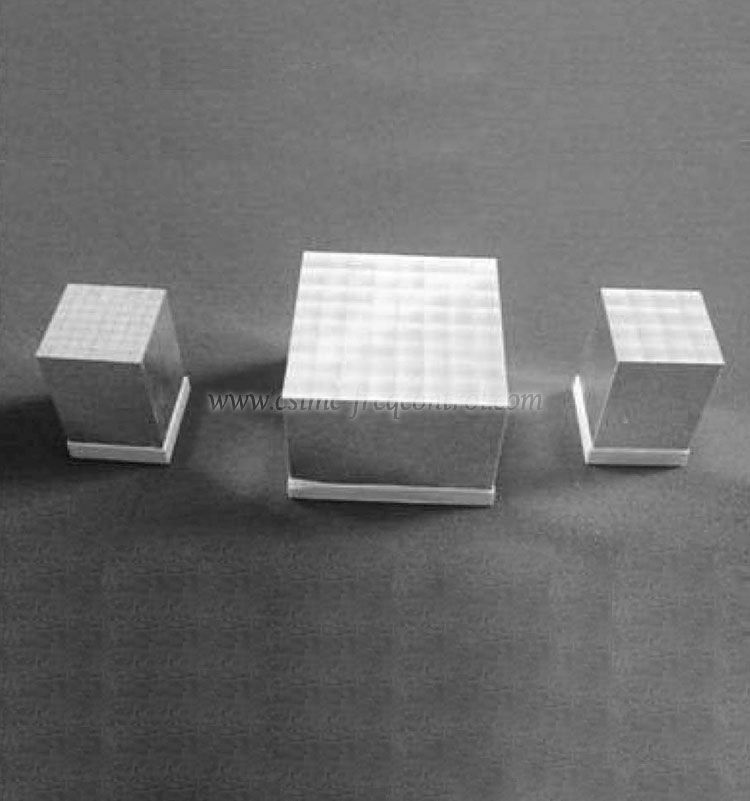
Piezoelectric wafers generate an electrical charge when mechanically stressed and deform when an electric field is applied. This bidirectional effect supports frequency control, acoustic-wave propagation, sensing, actuation, and signal filtering.
Quartz became a key frequency-control material during the development of radio communications because its elastic properties provide highly stable resonant behavior. Later, advances in thin-film deposition, photolithography, and RF packaging expanded the use of lithium niobate and lithium tantalate in surface acoustic wave (SAW), bulk acoustic wave, electro-optic, and piezoelectric MEMS technologies.
Today, the choice is rarely “which material is universally better?” The correct question is: which wafer provides the required coupling, stability, acoustic velocity, thermal behavior, and process compatibility for the target device?
| Performance factor | Single Crystal Quartz Wafers | Lithium-Based Piezoelectric Wafers | Practical design impact |
|---|---|---|---|
| Typical materials | Alpha quartz, commonly AT-cut, BT-cut, or other controlled orientations | Lithium niobate and lithium tantalate, with orientation selected for the acoustic mode | Material and cut determine resonance, temperature behavior, and coupling |
| Electromechanical coupling | Moderate; suitable for stable resonators and frequency references | Generally higher, especially for many SAW and acoustic-wave configurations | Higher coupling can support lower insertion loss and broader bandwidth |
| Frequency stability | Excellent when the cut, thermal compensation, and packaging are optimized | Good, but temperature coefficient and orientation must be carefully engineered | Quartz is often preferred for precision timing and low-drift oscillators |
| Acoustic velocity | Well characterized and highly repeatable | Often higher, depending on crystallographic direction and wave mode | Supports compact electrode spacing and high-frequency acoustic devices |
| Dielectric loss | Typically low and stable for frequency-control applications | Depends on composition, domain quality, conductivity, and processing | Influences Q factor, insertion loss, and RF power handling |
| Thermal behavior | Strong temperature performance in optimized cuts such as AT-cut quartz | Can offer useful temperature and pyroelectric characteristics, but may require compensation | Important in automotive, telecom, and industrial temperature ranges |
| Processing considerations | Well-established lapping, polishing, etching, and electrode processes | Requires careful control of wafer polarity, domain structure, surface damage, and pyroelectric charge | Process integration and cleanroom controls affect yield |
Quartz is widely used in crystal resonators because its mechanical Q factor can be high and its frequency-temperature response can be engineered through crystal cut and resonator design. An AT-cut quartz resonator, for example, is designed to reduce first-order frequency change around a selected temperature range.
Lithium niobate and lithium tantalate generally provide stronger piezoelectric coupling. This is valuable when a device requires efficient excitation, compact geometry, or a wide operating bandwidth. However, high coupling alone does not guarantee better frequency accuracy. Electrode loading, surface roughness, temperature drift, packaging stress, and spurious modes must also be controlled.
The electromechanical coupling coefficient is a major design parameter. Lithium-based wafers are often advantageous in SAW filters, resonators, acoustic delay lines, and optical-acoustic systems because their coupling can be significantly higher in selected orientations and modes.
Quartz remains competitive when low aging, low loss, predictable elastic constants, and long-term frequency stability are more important than maximum coupling. This is why Single Crystal Quartz Wafers continue to support clock oscillators, precision timing modules, quartz crystal filters, and frequency-control components.
Quartz is generally easier to manage in applications requiring a stable electrical baseline during temperature changes. Lithium niobate and lithium tantalate are pyroelectric materials, meaning temperature variation can generate electrical charge. This behavior can be useful in infrared detectors and sensors, but it may create transient voltage, electrostatic discharge, or handling risks during wafer processing.
For lithium-based wafers, manufacturers should evaluate:
CQT should be evaluated as a technical partner, not only as a wafer distributor. A reliable quotation should define the material grade, crystal orientation, diameter, thickness, tolerance, surface condition, edge profile, packaging, and inspection method.
For production control, inspection plans may reference SEMI M1 wafer dimensional terminology, IEC 60122-1 for quartz crystal units, and IEEE Std 176 for piezoelectric terminology and characterization principles. Surface texture reporting can be aligned with ISO 21920, while legacy programs may still specify ISO 4287 or DIN EN ISO 4288 terminology. The applicable standard should always be agreed in the purchase specification because not every standard applies to every wafer geometry or device type.
Not necessarily. High coupling can improve signal conversion and bandwidth, but the final device may still suffer from excess insertion loss, temperature drift, spurious modes, or poor aging. Device architecture and electrode design must be matched to the wafer.
Quartz is used across a broad frequency range, including high-frequency resonators and RF filters. The achievable frequency depends on wafer thickness, mode, electrode geometry, surface finish, and fabrication capability. Thin quartz structures can support demanding frequency-control designs.
They are related but not identical. Lithium niobate is often selected for strong piezoelectric and electro-optic performance, while lithium tantalate can provide useful temperature, dielectric, and material stability characteristics in specific applications. The correct choice depends on frequency, acoustic mode, temperature range, power level, and process flow.
Polishing is important, but yield also depends on TTV, bow, warp, subsurface damage, contamination, orientation accuracy, edge chipping, particle control, and lot consistency. A wafer with excellent visual appearance can still fail if its thickness profile is unsuitable for resonator fabrication.
Qualification requires application-specific evidence. Buyers should request a certificate of conformity, lot number, inspection results, material traceability, and—when required—sample evaluation under the actual electrode deposition, bonding, dicing, and packaging process.
A timing module for industrial control requires low frequency drift, predictable aging, and stable operation over a controlled temperature range. In this case, an optimized quartz cut is often the first option. The engineering team should prioritize Q factor, frequency-temperature coefficient, electrode compatibility, and long-term aging rather than selecting a wafer only because it has a higher coupling coefficient.
A wireless communication front end may require high electromechanical coupling, narrow electrode spacing, and low insertion loss. A lithium niobate or lithium tantalate wafer can be advantageous when the selected orientation and propagation direction provide the required SAW velocity and coupling. Surface roughness, lithography compatibility, and temperature compensation must be reviewed before mass production.
A sensor exposed to vibration and temperature cycling may use quartz for its stable resonant response or lithium-based material for higher signal conversion. The decision should be based on calibration drift, pyroelectric effects, package stress, shock testing, and environmental qualification—not on material category alone.
Suppose a device manufacturer receives wafers with a nominal thickness of 0.50 mm but experiences frequency variation after dicing. An investigation may find that TTV, bow, or orientation error—not the nominal thickness—causes the problem. Tightening the wafer specification, adding 100% visual inspection, and correlating incoming data with final device frequency can reduce avoidable process variation.
A professional supplier should also provide responsive technical communication. For example, CQT’s purchasing and engineering workflow can be structured around a 24-hour response target for technical inquiries, with agreed inspection criteria and sample feedback before volume release. Actual service levels should be confirmed in the commercial agreement.
Despite the growth of lithium-based materials, Single Crystal Quartz Wafers remain important because they combine mature supply chains, excellent frequency stability, established resonator processing, and strong long-term reliability. They are particularly suitable for quartz crystal units, oscillators, real-time clocks, filters, and precision frequency references.
The value of Single Crystal Quartz Wafers is not limited to the crystal itself. Consistent orientation, controlled thickness, low-defect polishing, clean packaging, and traceable inspection are equally important. These factors help manufacturers maintain stable impedance, resonance, and frequency output from lot to lot.
The main point of Performance Differences Between Quartz and Lithium-Based Piezoelectric Wafers is that quartz typically leads in frequency stability, mature processing, and low-aging performance, while lithium niobate and lithium tantalate often lead in piezoelectric coupling, acoustic bandwidth, and compact RF device potential.
For the best result, define the application first, select the crystal orientation second, and verify wafer geometry and inspection data before approving production. Whether the project requires Single Crystal Quartz Wafers or lithium-based piezoelectric wafers, CQT can help buyers compare material properties, establish tolerances, and develop a quality plan based on measurable requirements.
When evaluating the Performance Differences Between Quartz and Lithium-Based Piezoelectric Wafers, request samples, review standards such as IEC 60122-1 and IEEE Std 176 where applicable, confirm 100% inspection requirements when needed, and validate the wafers in the actual device process. This approach reduces qualification risk and supports reliable, scalable frequency-control manufacturing.


Copyright © Hangzhou Freqcontrol
Electronic Technology Ltd.
All Rights Reserved | Sitemap |
Powered by 







 中文


