Lithium Niobate Wafers and lithium tantalate wafers are both important piezoelectric materials for RF filters, but they serve different design priorities. Lithium niobate usually attracts engineers seeking high electromechanical coupling and wide frequency agility, while lithium tantalate is often selected for stronger temperature stability, lower pyroelectric risk, and predictable long-term operation.
For purchasing teams, the decision is not simply a comparison of material names. The real questions are whether the wafer can meet the target frequency, insertion loss, bandwidth, power level, thermal range, reliability requirement, and production yield at an acceptable total cost. The following comparison focuses on those practical purchasing and engineering concerns. CQT can support material selection and RF component development when the application requires a balanced evaluation of wafer performance, process compatibility, and supply consistency.
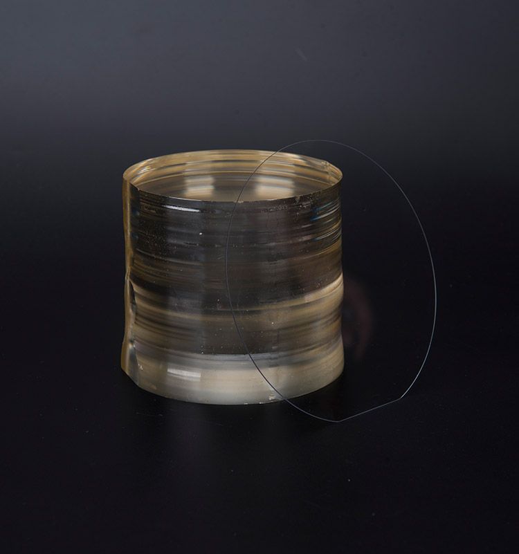
Lithium niobate and lithium tantalate are both ferroelectric single-crystal materials with strong piezoelectric behavior. Their crystal orientation, cut, electrode structure, and film thickness have a direct effect on the final filter response.
In practice, the material is only one part of the filter stack. A well-produced lithium tantalate wafer can outperform a poorly processed lithium niobate wafer, especially when the application is highly sensitive to temperature drift, spurious modes, or production variation.
Purchasers should request the exact crystal cut and orientation instead of accepting a general description such as lithium niobate wafer or lithium tantalate wafer. Different cuts can produce substantially different coupling, frequency temperature behavior, mode excitation, and manufacturability.
The following table provides a practical comparison for early material screening. Values are representative engineering ranges rather than universal specifications. The final result depends on wafer cut, device architecture, electrode material, film design, packaging, and operating frequency.
| Parameter | Lithium Niobate | Lithium Tantalate | Purchasing meaning |
|---|---|---|---|
| Electromechanical coupling | Typically higher | Typically moderate | Lithium niobate is often better for wide bandwidth and strong transduction. |
| RF bandwidth potential | High, depending on cut and structure | Moderate to high, depending on design | Choose lithium niobate when bandwidth is a primary requirement; verify spurious mode control. |
| Temperature stability | Moderate and strongly cut dependent | Generally better in many filter designs | Lithium tantalate can reduce frequency drift and calibration burden. |
| Pyroelectric behavior | More pronounced concern | Generally lower concern than lithium niobate | Lithium tantalate may be easier to manage during handling and temperature cycling. |
| Power handling | Good when thermal and electrode design are optimized | Good and often attractive for stable commercial operation | Evaluate power density, heat removal, aging, and packaging together. |
| Insertion loss potential | Can be very low with an optimized structure | Can be low and stable across temperature | Actual loss depends heavily on electrode resistance, acoustic leakage, and packaging. |
| Frequency drift | Can be more noticeable over temperature | Often lower in comparable designs | Lithium tantalate can reduce retuning and system compensation requirements. |
| Spurious response control | Requires careful mode and electrode design | Often easier to manage in conservative designs | Measure the complete passband and stopband, not only the center frequency. |
| Processing sensitivity | High, especially for wideband structures | Moderate to high | Supplier process control and test capability are essential. |
| Typical selection advantage | Wide bandwidth, high coupling, compact high-performance designs | Temperature stability, predictable operation, robust commercial designs | Choose according to the system priority rather than material popularity. |
Parameter comparisons are useful for screening, but they should not be treated as guaranteed device specifications. For example, higher coupling does not automatically mean lower insertion loss. It may increase bandwidth while also making mode control, matching, and spurious suppression more difficult.
Similarly, better temperature stability does not automatically mean lower total filter cost. Lithium tantalate may reduce compensation requirements, but the wafer price, electrode process, and design architecture must still be evaluated together. A purchasing team should compare the total cost of ownership rather than only the price per wafer.
Lithium niobate is often attractive when the filter must cover a relatively wide frequency range or support strong acoustic coupling in a compact structure. Engineers may obtain a wider passband without making the device excessively large, but the design may require more careful control of transverse modes, reflections, and spurious responses.
Lithium tantalate can provide a more conservative design path. Its moderate coupling may limit the maximum achievable bandwidth in some structures, but it can support predictable passband behavior and stable production when the filter specification is not extremely wide.
Temperature stability is one of the clearest practical differences between the two materials. A filter made with lithium niobate may show greater frequency movement as the device temperature changes, particularly if the crystal cut and compensation design are not optimized.
Lithium tantalate is often preferred for products exposed to repeated temperature changes, outdoor conditions, or strict frequency masks. Its more stable thermal behavior can reduce the amount of electronic correction required by the system.
However, neither material should be described as temperature independent. The final frequency response is also affected by:
RF filter wafers do not store energy, so battery life cannot be compared in the same way as battery capacity. The relevant question is whether the filter allows the transmitter and receiver to operate with lower total power while maintaining the required link quality.
A filter with lower insertion loss can reduce the power that a transmitter must generate to reach the same effective output. In a receive chain, lower loss can improve sensitivity and reduce the need for additional amplification. These effects may contribute to longer battery life, but the actual improvement depends on duty cycle, transmit power, amplifier efficiency, radio architecture, and network conditions.
For a purchasing decision, request module-level power data instead of accepting a general claim that one wafer material improves battery life.
Long-term stability depends on crystal quality, electrode adhesion, package design, humidity protection, thermal cycling, and RF power stress. Lithium tantalate is frequently considered when predictable behavior over temperature and time is a priority. Lithium niobate can also deliver reliable service when the crystal cut, processing conditions, and package are properly optimized.
Before approval, qualification testing should include:
Lithium niobate is therefore a strong choice for performance-led designs, but the purchasing team should budget for tighter process control and more detailed RF characterization.
Lithium tantalate is often the safer option for stable, repeatable RF operation, but it should not be selected solely because it has a reputation for thermal stability. The complete filter specification must still be verified through measured samples.
Lithium niobate is generally a strong candidate for engineering teams developing compact RF filters with wide passbands, high coupling, or demanding acoustic transduction efficiency.
These buyers should be prepared to specify crystal cut, temperature compensation, spurious response limits, and detailed wafer uniformity requirements.
Lithium tantalate is generally a strong candidate for products that operate across changing temperatures and require stable frequency response over long service periods.
These buyers should confirm that the selected wafer can meet the required bandwidth and insertion loss without excessive device area or additional matching complexity.
When the product specification is still changing, the most efficient approach may be to test both materials using comparable filter architectures. This avoids making a decision based on theoretical material data alone.
A supplier quotation should include more than wafer size and price. Purchasing teams need enough information to determine whether the material is compatible with the intended RF process.
A strong first sample is not enough for production approval. The supplier should demonstrate stable process control across multiple lots and provide a clear method for handling nonconforming material.
Important supplier evaluation points include:
CQT can be considered when the project requires coordinated evaluation of wafer characteristics, RF filter targets, supply requirements, and application conditions. The key objective is to match the wafer specification to the device design rather than purchase a material based on a generic performance ranking.
The most practical conclusion is that lithium niobate is usually favored for high coupling and wide bandwidth, while lithium tantalate is usually favored for thermal stability, predictable operation, and production robustness.
| Primary project priority | Preferred starting material | Reason |
|---|---|---|
| Maximum bandwidth | Lithium niobate | Higher coupling can provide more design bandwidth. |
| Minimum temperature drift | Lithium tantalate | It often offers more stable frequency behavior. |
| Compact acoustic structure | Lithium niobate | Strong transduction can support compact designs. |
| Long-term commercial stability | Lithium tantalate | Stable thermal behavior can reduce compensation requirements. |
| Lowest possible module power | Either, after measurement | Battery impact depends on complete RF chain loss and system behavior. |
| Fastest material selection | Use comparative samples | Measured filter data is more reliable than general material assumptions. |
Purchasers should select lithium niobate wafers when the design demands wide bandwidth, high coupling, and compact RF integration, provided that temperature drift, pyroelectric behavior, and spurious modes are controlled. Lithium tantalate wafers are often the better choice when stable frequency response, predictable operation, and production consistency are more important than maximum bandwidth.
The best decision should be based on a controlled comparison of wafer quality, filter response, temperature behavior, power aging, manufacturing yield, and total cost. For teams developing a new RF filter platform, CQT can help organize the evaluation around the actual product requirements instead of relying on isolated material specifications.
In the end, Lithium Niobate Wafers are not universally better or worse than lithium tantalate wafers. The correct material is the one that delivers the required RF performance, battery-efficient system operation, long-term stability, and production reliability for the intended application.


Copyright © Hangzhou Freqcontrol
Electronic Technology Ltd.
All Rights Reserved | Sitemap |
Powered by 







 中文


